上海埃飞科技
Worldwide Technology(S. H)上海埃飞科技
Worldwide Technology(S. H)产品展示

CAST satellite signal simulator
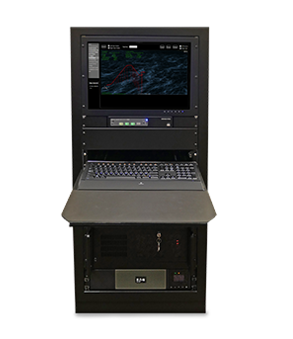
CAST仿真器SBAS模型可用于通过WAAS,EGNOS,MSAS和印度GAGAN项目SBAS精度增强评估GPS接收机。提供的SBAS模型符合RTCA DO-229 MOPS(最低运行性能标准)规范。用户可以在模拟运行期间指定并模拟最多两颗SBAS卫星。The CAST simulator SBAS model can be used to evaluate GPS receivers through WAAS, EGNOS, MSAS and India GAGAN project SBAS accur
GPS constellationedit
Power level control: The CAST simulator allows users to control the power level of each SV individually and independently of each other. The signal level output range of the CAST simulator is -190 dBW to -135 dBW on L1 and L2, which can be controlled in steps of 1 db. The CAST simulator also allows input of cable and coupling losses, thereby providing an easy way to define power settings when wiring configuration requirements change.
Ephemeris/Almanac Definition: The CAST simulator includes an Ephemeris/Almanac editor that allows users to define a single ephemeris or almanac message set to use data and selected satellites within 50 Hz of transmission. The editor provides users with the ability to customize 50 Hz messages for normal, multi-path or fraudulent application data. The option editor in the ephemeris and almanac allows the user to propagate the message data to a specified time. Real-world ephemeris and almanac data from various GPS constellation files can also be uploaded to the system.
Modifiable navigation message: The CAST simulator can modify any part of the 300-bit navigation message, including satellite health messages and clock errors.
RAIM events: The CAST simulator can modify the receiver's autonomous integrity monitoring (RAIM) conditions. These can be defined by simulating running time and satellites. The operator can modify the satellite range, drift and/or add noise to the satellite signal.
The range step event causes the pseudorange of the specified satellite to be adjusted at the specified simulation time. Perform the same distance step adjustment on all subsequent pseudorange values of the specified satellite until another RAIM distance step event of the satellite is found.
Satellite drift causes the pseudorange and pseudorange rate of the specified satellite to be adjusted by the drift rate starting at the specified event time and continuing for a defined event period.
Once the final pseudorange caused by the range drift is achieved, the total range adjustment will be made to all subsequent pseudoranges of the satellite until another RAIM event occurs.
The range noise event causes the pseudorange and pseudorange rate of the designated satellite to be adjusted through random rate changes in each simulator update period within the specified noise period.
SA modeling: The CAST simulator contains a simulated version of SA. This is a mathematical model that simulates the SA clock jitter process. It generates satellite clock disturbances by passing pseudo-random white noise through a second-order linear filter. The parameters that define the model are the power spectral density (PSD) of the white noise, the time constant of the filter and the damping ratio.
Ionospheric modeling: The CAST simulator simulates the GPS signal delay caused by the ionosphere. It has five user-selectable models: single-frequency user model, uniform density model, constant rate model, Chapman model and extended Klobuchar model. All models include frequency dependence.
Tropospheric modeling: The CAST simulator simulates the GPS signal delay caused by the troposphere through a model that is sufficient for all users. The model can be easily modified in the system to include wet and dry components.
Multipath modeling: The CAST simulator simulates multipath by using GPS satellite RF signal generators to simulate reflected signals. The intensity of the reflected signal is fixed relative to the direct signal, but its delay will vary according to a simple geometric reflection model.
Vehicle parameters
Vehicle types: Users can select the following vehicle types to simulate their dynamic movement: airplanes, helicopters, ships/submarines, trucks and space vehicles.
Antenna lever arm/gain mode: The user can limit the distance between the GPS antenna of gravity and the center of the vehicle by using the antenna lever arm. The antenna gain pattern function of the CAST simulator supports the use of the built-in editor to input the two-dimensional antenna pattern.
Using externally generated files containing patterns can support more complex or three-dimensional patterns. In this way, they can accurately simulate antenna performance based on the location of the antenna on the auxiliary vehicle.
Vehicle contouring: "Vehicle contour model" is a user interaction process, and the shadow effect of each 5 degree point of the car body needs to be defined. The user inputs the outline of the vehicle, and the result of the existing outline is displayed in the form of rectangle or polar coordinates that the operator can select. This function allows the user to define the shadow of the GPS antenna, which may be caused by various effects, such as those caused by certain parts of the modeled vehicle.
The usual application is to make a good estimate of the effect of the aircraft's vertical stabilizer. As far as AWACS is concerned, CAST supports military systems in multiple avionics laboratories, and the large surveillance radar at the rear of the fuselage is an important signal blocker.
Trajectory specification: The CAST simulator supports three ways of constructing/importing trajectories:
1. User-defined-the user can generate the trajectory by defining the overall task profile. This is done by entering motion primitives to create a dynamic scheme. After entering each parameter, it will be appended to all previous motion primitives until the required flight profile is created. After the creation is complete, you can save the generated configuration file for later use. CAST has standardized its scenario motion format so that various laboratories equipped with CAST can exchange flight scenarios to help explore the performance of the navigation system.
2. External trajectory-The actual six-degree-of-freedom (6-DOF) dynamic trajectory data file from the field task can be read into the CAST simulator and used as a motion definition.
3. Real-time input-an optional interface that allows users to send six-degree-of-freedom vehicle trajectory data from an external source to the CAST simulator via Ethernet.
Waypoint navigation: The CAST simulator supports waypoint navigation, which enables flexible setting and positioning of dynamic exercises.
Initial parameters: The user can fully control the initial initial parameters, including real initial latitude, real initial longitude, real initial datum height, real initial average sea level, real initial speed, real initial course, sea conditions and ship motion. You can also specify the GPS week, GPS week cycle counter, number of seconds, and the date and time of the simulation start.
Real model comparison/performance evaluation
The performance evaluation module provides the function of using the original measured values and filtered data received from the tested navigation system and comparing them with the real data that defines the motion of the simulator. The CAST simulator calculates the difference between the two and displays the results in graphs and tables.
Standard interface
The instrument port interface (RS-422) and MIL-STD-1553B interface are standard equipment on the CAST simulator. The IEEE-1394 interface can also be used as an option, because modern military avionics have now adopted this bus architecture.
Auxiliary simulation data can be provided to UUT through various interface standards on the CAST simulator, most of which are specific 1553 data bus messages. For applications that require assistance to support the navigation system under development, CAST can provide the necessary minor modifications.
The CAST simulator records all user-specified test data from the internal truth model of the simulator and interface data messages from the UUT. In addition to the standard instrument port data (ICD-GPS-215, ICD-GPS-150/153), test engineers can also collect and record various navigation-related messages from the 1553B bus.
CAST Simulator standard options
Anti-interference test ability
The CAST simulator provides controllable and repeatable support for testing the anti-jamming performance of the receiver. The system includes a mechanism for commanding a programmable interference signal source in real time when flying a specific flight path in a tanking scene, or when using an aviation model to define a flight path from the outside.
The size, frequency and various types of modulation of the interference source can be controlled. In addition, the CAST simulator provides users with extensive capabilities to explore receiver performance in the presence of obvious satellite spoofing. Spoofing is a point source that can transmit GPS signals with the same C/A, P or even P(Y) code to any GPS satellite. This file can be created at a nearby ground location in the simulator to destroy the receiver's ability to track the correct satellite. The deception source can change its characteristics in response to movement through weapons or user-defined algorithms. All of this support is dynamic.
The CAST simulator can predefine the flight path of the interference source. The system can simulate the predetermined mode of the interference source's flight, and automatically and dynamically adjust the signal strength of the interference signal according to the variation range of the UUT relative to its predetermined movement.
The modulation type on the interfering signal can also be commanded dynamically.
The CAST simulator has the ability to interface with the GPS/INS navigation system under test, so that it can record navigation messages from GPS receivers that report interference-related values. Usually, these parameters include J/S ratio, satellite azimuth and elevation, and sometimes even individual satellite pseudoranges. By making these records available to users, the process of creating test reports is greatly simplified.
Real-time test
The real-time trajectory input option allows users to send six-degree-of-freedom vehicle trajectory data to the CAST simulator from an external source of each CAST real-time ICD via Ethernet.
Other SV
Other satellites can be added in increments of sixteen.
SBAS simulation
The CAST simulator SBAS model can be used to evaluate GPS receivers through WAAS, EGNOS, MSAS and India GAGAN project SBAS accuracy enhancement. The provided SBAS model complies with RTCA DO-229 MOPS (Minimum Operating Performance Standard) specifications. The user can specify and simulate up to two SBAS satellites during the simulation run.
SBAS correction is applicable to the following situations:
-Ionosphere
-Ephemeris
-Clock AF0, AF1, AF2 error
-RAIM activities
-Selective supply
If an extreme constellation error is detected that exceeds the limit specified in RTCA DO-229, the SBAS correction will automatically indicate a "do not use" condition.
Terrain occlusion program (TOP)
TOP provides a real-time check of the visibility of the satellite, which accounts for the terrain around the GPS receiver. The communication between the CAST simulator and the TOP computer is carried out through an Ethernet link. The CAST system provides a list of satellites that are usually visible to TOP every second. TOP uses the surrounding terrain database to check the line of sight of each proposed satellite to determine visibility. TOP returns the visibility status of each suggested satellite, which takes into account the occlusion factor of the terrain. TOP does not require the user to take any measures, but the user can control the viewpoint to visualize the terrain, so as to obtain different perspectives on the terrain that affects the simulation.
Visualization: TOP provides users of the CAST simulator with visual cues on the terrain to be simulated during operation. The terrain is displayed in an animated wireframe view, and the simulated position of the observation point relative to the receiver can be adjusted by the user. This allows users to simulate terrain effects on the receiver to help quickly identify performance issues.
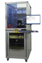
因用于机器人各方面应用且与大多数机器人类型兼容,AutoCal系统可以检测出机器人自身构造和工具中心点(TCP)的 突然改变或偏离,并且该系统无需人为干涉就自动地更正这些误差。
AutoCal系统-Dynalog的先进水平校准技术,Dynalog是机器人单元标定技术的世界领导者。它的主流产品DynaCal 系统,被应用于离线的机器人单元校准,并作为最精确的和技术先进的机器人校准程序为许多机器人制造商和终端使用者所接受。AutoCal 系统将已证实的DynaCal校准技术结合到一个在线的全自动系统中,该系统专为程序控制和复原而设计的,价格低廉。
AutoCal系统提供在线的机器人校准方案,旨在快速和自动地保证机械设备的工作性能。因用于机器人各方面应用且与大多数机器人类型兼容,AutoCal系统可以检测出机器人自身构造和工具中心点(TCP)的 突然改变或偏离,并且该系统无需人为干涉就自动地更正这些误差。这意味着不用猜测哪里会出错,不用浪费宝贵时间在机器人程序重复校准上,产品品质无任何损失。
AutoCal系统-Dynalog的先进水平校准技术,Dynalog是机器人单元标定技术的世界领导者。它的主流产品DynaCal 系统,被应用于离线的机器人单元校准,并作为最精确的和技术先进的机器人校准程序为许多机器人制造商和终端使用者所接受。AutoCal 系统将已证实的DynaCal校准技术结合到一个在线的全自动系统中,该系统专为程序控制和复原而设计的,价格低廉。