上海埃飞科技
Worldwide Technology(S. H)上海埃飞科技
Worldwide Technology(S. H)产品展示

Proton exchange membrane fuel cell test system
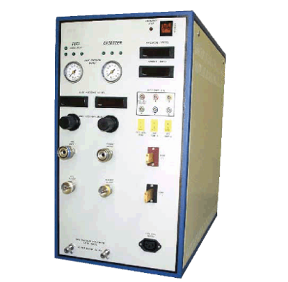
The biggest feature of the system is the modular setting in the true sense. Different systems can be customized according to the specific needs of customers.
The Fideris fuel cell test system in the United States is the first unit in the industry to engage in the research of fuel cell test systems. It has been more than 20 years since 1992. The company applied for the first patent for a fuel cell test system in the United States in 1994. Patent number: US Patent (5,512,831). Later, he applied for 7 patents in electronic load, humidifier and back pressure.
The biggest feature of the system is the modular setting in the true sense. Different systems can be customized according to the specific needs of customers. The types of fuel cells that the system can test include: direct methanol fuel cell test system, solid oxide fuel cell test system, proton exchange membrane fuel cell test system, molten phosphoric acid fuel cell test system... The test fuel cell power can range from 1W to 100KW.
Product advantages
+Ideal for fuel cell R&D, quality control, and durability testing
+ Flow control of up to four gases
+ Optional back pressure control for exhaust gas
+Protection purge system for fuel gas failure safety
+The load is compatible with AC impedance measurement
+Low resistance load makes it possible to test a single battery without increasing the power supply
+Fuel cell heater control
+Auxiliary equipment input and output
+Complete key switch system, including all necessary interfaces, connections, hardware and software
technical parameter
Gas control
Reactive gas control: flow controller
Maximum number of reactive gases
Maximum reaction gas flow rate: According to the instructions, a total of four gas channels are divided into fuel and oxidizer channels
Standard 10 liters per minute per reaction gas channel
Input reaction gas pressure range: 100-170 psi
Purification blowing system pressure range: 100-130 psi
Blowing system valve: normally open, computer-controlled valve
Exhaust gas phase separator: optional
Exhaust back pressure control: optional, manual or computer control is optional
Electronic load
Type: MOSFET variable resistance load box
Current measurement: panel shunt
Maximum current level: 5 Amp or 50 Amp
Maximum voltage level: 5, 10, or 20 Volts (other voltages are optional)
Maximum power consumption: 250 Watts
Nominal short-circuit resistance: <1.25 milliohms
Corrosion protection: gold-plated protection for all key components
Power requirements
Voltage: 85-250 VAC
Frequency: 47-440 Hz
Power consumption: 350 Watts plus fuel cell heater exchange plug
Unit heater exchange plug
Voltage/Frequency: Same as the main power supply unit
Maximum current: 3.5 Amps
Controller input: K-type thermocouple
Installation requirements
Operating space: back: 6", right: 6", left: 6", top: 0"
Physical characteristics
Size: 29" deep; 21.5" high; 12" wide
System weight: 65-80 pounds (depending on configuration)
Operating environment 40-100 degrees Celsius, 85% relative humidity
Frame placement level Indoor
Front panel control and display/EM
Fuel cell voltage 3-1/2 digits backlit LCD display
Fuel cell current 3-1/2 digit backlit LCD display
Back pressure target pressure (optional): 0-100 psi analog meter
Actual back pressure (optional): 3-1/2 digits backlit LCD display
Emergency stop state flashing red LED
Gas pressure status display Green LEDs
Blowing system pressure status Green LED
Front panel interface (all required interface cables are provided)
Fuel cell supply fuel connection: 1/4" Swagelok quick connection
Fuel cell fuel return interface: 1/4" Swagelok quick interface
Fuel cell oxidizer supply interface: 1/4" Swagelok quick interface
Fuel cell oxidizer return interface: 1/4" Swagelok quick interface
Load interface: banana interface, scre, or bolt fastening
Fuel cell voltage: LEMO (3' matching cable is provided)
Fuel cell temperature input Micro K (thermocouple provided)
Auxiliary input and output: LEMO (3' matching cable is provided)
Auxiliary temperature input (matching interface provided): 2 micro K thermocouples
Switch socket output: IEC-320 output (matching cable provided)
Back pressure detection port (optional): 1/8" Swagelok
Back panel interface
Reactive gas input: 1/4" Swagelok
Exhaust emission: 3/8" Swagelok
Water discharge (optional): 1/8" Swagelok
Control air input (if necessary for configuration): 1/4" FNPT
RS-485 communication input and output: DB-9
Hard-wired emergency stop input: 4-pin connector (matching of jumpers, pipes and sockets are provided)
Hard-wired emergency stop output: 4-pin connector (matching tube and needle are provided)
Safe state remote control input and output: 7-pin interface (jumper matching provided)
Power input: IEC-320 (Matching cable is provided)
Software Fideris FCPower TM software
technical parameter
Gas control
Reactive gas control: flow controller
Maximum number of reactive gases
Maximum reaction gas flow rate: According to the instructions, a total of four gas channels are divided into fuel and oxidizer channels
Standard 10 liters per minute per reaction gas channel
Input reaction gas pressure range: 100-170 psi
Purification blowing system pressure range: 100-130 psi
Blowing system valve: normally open, computer-controlled valve
Exhaust gas phase separator: optional
Exhaust back pressure control: optional, manual or computer control is optional
Electronic load
Type: MOSFET variable resistance load box
Current measurement: panel shunt
Maximum current level: 5 Amp or 50 Amp
Maximum voltage level: 5, 10, or 20 Volts (other voltages are optional)
Maximum power consumption: 250 Watts
Nominal short-circuit resistance: <1.25 milliohms
Corrosion protection: gold-plated protection for all key components
Power requirements
Voltage: 85-250 VAC
Frequency: 47-440 Hz
Power consumption: 350 Watts plus fuel cell heater exchange plug
Unit heater exchange plug
Voltage/Frequency: Same as the main power supply unit
Maximum current: 3.5 Amps
Controller input: K-type thermocouple
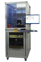
因用于机器人各方面应用且与大多数机器人类型兼容,AutoCal系统可以检测出机器人自身构造和工具中心点(TCP)的 突然改变或偏离,并且该系统无需人为干涉就自动地更正这些误差。
AutoCal系统-Dynalog的先进水平校准技术,Dynalog是机器人单元标定技术的世界领导者。它的主流产品DynaCal 系统,被应用于离线的机器人单元校准,并作为最精确的和技术先进的机器人校准程序为许多机器人制造商和终端使用者所接受。AutoCal 系统将已证实的DynaCal校准技术结合到一个在线的全自动系统中,该系统专为程序控制和复原而设计的,价格低廉。
AutoCal系统提供在线的机器人校准方案,旨在快速和自动地保证机械设备的工作性能。因用于机器人各方面应用且与大多数机器人类型兼容,AutoCal系统可以检测出机器人自身构造和工具中心点(TCP)的 突然改变或偏离,并且该系统无需人为干涉就自动地更正这些误差。这意味着不用猜测哪里会出错,不用浪费宝贵时间在机器人程序重复校准上,产品品质无任何损失。
AutoCal系统-Dynalog的先进水平校准技术,Dynalog是机器人单元标定技术的世界领导者。它的主流产品DynaCal 系统,被应用于离线的机器人单元校准,并作为最精确的和技术先进的机器人校准程序为许多机器人制造商和终端使用者所接受。AutoCal 系统将已证实的DynaCal校准技术结合到一个在线的全自动系统中,该系统专为程序控制和复原而设计的,价格低廉。