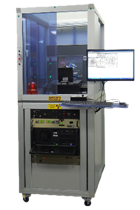
The EUV tube provided by Laser nanoFab GmbH is a compact and user-friendly extreme ultraviolet (EUV) source for metrology. The source is based on advanced microfocus X-ray tube technology that has been extended to the EUV spectral range.
The EUV emission is generated by electrons colliding with solid state targets. This concept guarantees debris-free operation, well-defined performance characteristics and excellent long-term temporal and spatial stability.
EUV POWER
At present, EUV powers of up to 20 μW (2π sr, 2% bw) are achieved.
STABILITY
The EUV source has excellent long-term stability. In continuous operation the fluctuations were measured over a period of three days and typically less than 1%.
SOURCE SIZE
The source size is below 10 µm and can be varied via operation voltage and current. Source sizes of 100 μm and more are possible (full width at half-maximum).
INTERFACE
The EUV tube comes with a standard DN 16 CF vacuum flange, so connection to your vacuum setup is easy. The EUV emission cone is centered on the flange axis.
OPEN DESIGN
Customer-specific adaptations are possible.
APPLICATIONS
► At-wavelength characterization of EUV optical components, e.g. multilayer mirrors, masks, or filters
► Off-synchrotron calibration of EUV tools, e.g. spectrographs and energy monitors
► EUV imaging and microscopy with high lateral resolution KEY FACTS
► Compact set-up, easy and intuitive operation
► Debris-free operation
► Excellent long-term temporal and spatial stability
► Very low running costs
► Computer-controlled (start-up, centering, focusing, operation)
 Emission
The EUV tube is equipped with a solid-state target on which electrons are focused to generate EUV emission. Outside the target, only electrons and photons are present. The target is not ablated and the source does not emit particle debris or ions.
The emission can be controlled via the control software of the EUV tube in terms of accelerating voltage, current and focusing of the electron beam on the target.
EUV emission spectrum and power
The emission spectrum of the source has its maximum at 13.5 nm, and it covers about 1 nm around this maximum (Figure 1, green curve). Inside 2% bandwidth at 13.5 nm up to 20 μW are emitted into 2π sr. From this emission into half-space, an angular range of 30° can be used at the source output.
If the spectrum is to be narrowed down to 2% bandwidth at 13.5 nm, this can easily be achieved by reflection from two ML mirrors, resulting in a nearly perfect EUV spectrum (Figure 2, blue curve).

Figure 1: Emission spectrum of the EUV tube between 12 nm and 15 nm (green) and spectrally narrowed after reflection at two multilayer mirrors (blue)
Stability of EUV emission
The source works as stable and reliable as an industrial quality X-ray tube. After a short warm-up time the emission is very stable, in particular there are no emission fluctuations as they occur with plasma-based sources. We measured fluctuations of less than 1% over three days (Figure 2).

Figure 2: Typical stability of EUV tube operation.
Out of band emission
The source generates following relevant emissions:
Solid target: L2, Ls at about 92 eV (EUV, 13.5 nm)
Solid target: Li at 150 eV (8.3 nm), Kα at 1.74 keV and Kβ at 1.84 keV (0.7 nm)
Visible light from the EuV-tube's filament
Scattered electrons
The EUV emission happens due to the L2,3 transition. The other emissions can be easily blocked if unwanted: K emission can be effectively filtered by reflection on a EUV multilayer mirror. Scattered electrons can be deflected by a static magnetic field. Visible light can be blocked by a Zr filter.
The solid target has a typical damage threshold of 1-5 kW/mm². When exceeding the damage threshold the target damage is usually well localized to a few 100 µm. The target can be simply rotated by a small angle to change to a new and undamaged spot.
EUV tube setup and emission direction

Figure 3: Top view with emission cone (blue)

Figure 4: Side view with emission cone (blue)
The head of the tube can be mounted in four different orientations (steps of 90°).

Figure 5: The emission cone (max. 30° full angle) originates 15.4 mm behind the
front face of the DN 16 CF flange